1/13/18

Measuring Low Power Mode 3.5 in MSP430FRx Microcontroller

I took some notes while profiling the Low Power Mode 3.5 (LPM3.5) in MSP430FR2311IPW20 Microcontroller from Texas Instruments.

Fig 1. The Setup is very minimal. I used a TSSOP-20 breakout and powered it with CR2032 battery. The current line is monitored by µCurrent GOLD (custom made).

Fig 2. Scope Setup: CH1 is connected to the µCurrent output. CH2-CH3 (differential) is used to probe the GPIO (P1.6).

Fig 3. Complete Setup. MSP430FR4133 Launchpad is used for programming.
The LPM3.5 example code provided by Texas Instruments is used for this experiment (Available here).

The code is straightforward. To summarize, it initializes XT1 (32Khz) as the main clock, check if it is a cold start or waking up from Low Power mode. When it is a cold start, it initializes the RTC with clock source as XT1, and RTC issues wake up interrupt every One second. When waking up from the Low Power mode, it restores the state of the Port 1 from Backup memory and enables the interrupt. In the RTC ISR, P1.6 is toggled and the state of Port 1 is saved in the Backup memory.

The state of the required port (in this case Port 1) need to be saved before going into the LPM3.5, otherwise, the MCU will lose it state.

The idea is to measure the time taken for the microcontroller from sleep mode and time taken to serve the RTC interrupt service routine.

Fig 4. CH1 Shows the µCurrent output. µCurrent is in 1mV/µA mode. So 1mV indicates 1µA. Violet is CH2-CH3 to profile the GPIO Pin.
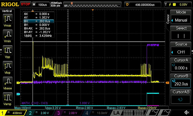
Fig 5. Time taken for the Wakeup.
From the above image, it is clear that the time taken from the wake is 292 us. The datasheet Table 6-1. Operating Modes mentions the time taken is 350 us. While waking up, there is a peak current consumption of 1.352 mA.

Fig 6. After waking up from the Sleep mode, it takes around 600 uS to select the 32Khz crystal. The current consumption during this period is roughly 240 µA.
Fig 7. It takes around 48 uS after entering the RTC ISR to toggle the GPIO.
Fig 8. After toggling the GPIO, 38 uS is required to save the state of PORT1 to Backup memory and enter the LMP3.5 Sleep mode.
You get more insights from the scenario when GPIO transition from High to Low.

Fig 9. Hi to Low transition of P1.6

Let me explain what's happening here. The default state of the GPIO is Low. So, when the MCU wakes up, P1.6 is pulled to low (resetting to its default state). So from the above image, it is clear that the time taken for the MCU to wake up is 262 uS, which is well within the limit (350 uS).

Fig 10. Time taken to restore the Port 1 state.
The time taken to restore the Port 1 GPIO state is 648 us. The in-between time is spent on selecting the crystal pin and setting up the crystal. I assume that most of the time is spent on checking for the oscillator flag.

Fig 11. Current spike before restoring the Port 1 state.
There are some current spikes before restoring the Port 1 state. Probably, the spikes are due to the data read from the Backup memory. If this assumption is correct, then the time taken for the read is 14 uS.

Fig 12. After toggling the GPIO, 36 uS is required to save the state of PORT1 to Backup memory and enter the LMP3.5 Sleep mode. (Matches with Fig. 8)
To summarize, let's highlight the events.

Fig 13. 

0 - MCU in LPM 3.5 Sleep mode.
1 - MCU wakes up from the Sleep mode, resets the Watchdog timer.
2 - Initializes the GPIO and selects the crystal pins.
3 - Sets the main oscillator clock to XT1.
4 - Reads the state from Backup memory and restores it.
5 - RTC ISR serviced.
6. Saves the state in Backup memory and goes back to LPM3.5.


So far, I focused on the time taken for the various event. Let's focus on the Y-Axis (Current). Which is the important feature of the MPS430 series.

As mentioned earlier in the setup, custom-made µCurrent GOLD is used in 1mV/µA mode. So, 1mV division in the scope represents 1µA current consumption in the Device under test (DUT).

Fig 14. Current spikes occur every second, which indicates the device waking up every one second.
The violet line shows the integration of current over the time (Area under the yellow curve). It is measured around 28 mVs which indicates a current consumption of 28 µA over a period of one second 2.4 seconds, which indicates that the current consumption is 11.83 µA/sec. But this measurement might be deceiving as the scope has an error due to the offset. (Explained in the comments of this EEVBlog video).

In the following figure, you can notice the time scale is set at 100ms and the microcontroller is set to wake up every 10 seconds.

Fig 15. Integration using Math and Measurement functions.
The Math function shows the Area under the curve is 11.6 mVs (Vs because the BX-AX is 1s) and at the bottom, the Area over the full screen is measured as 12.9 mVs (over 1.2s) which is matches our previous measurement.

Fig 16. Zoomed in position of LPM current consumption.
Going on, in the above image, you can notice the current spikes at around 36 Hz frequency. This indicates the RTC counter counting up (It is supposed to be 32 Hz, but I am not sure why I am getting 36 Hz, maybe the crystal is not compensated which causes a drift? 🤔 ) During the RTC count up, the current consumption is around 15 µA.

Fig 17. During the sleep mode, the current peaks are around 7 µA.

Finally, I made the RTC interrupt every 10 seconds to measure the average current consumption during the LPM 3.5 mode with the multimeter.

Fig 18. 1mV/nA is selected. Hence the average consumption is 531 nA.
I could measure 531nA during the LPM 3.5 sleep mode which is well within the limit mentioned in the datasheet (0.71 µA) See Table 6-1. Operating Modes in the datasheet.

Overall, the measurements are well within the limits mentioned in the datasheet.


7/11/15

My first experience in Hackanthon - iTech2015

I came across a group post in Facebook which says there;s a IoT hackanthon happening in Banglore. Ah, I am going to move to IoT team next month and this would be a good chance to get exposed myself to the technology. And the best part about the hackanthon - There's a takeaway kit. Sounds good. There's a catch. You have to submit you idea and they will shortlist the team. So Mervin and I assembled in Karthick Singaram's place to brainstorm the idea. I pitched my traffic signal controller idea which controls the traffic when a ambulance comes close by it. It doesn't impress them well. But the team leader Singaram had a brighter idea. A bar code scanner fixed into the trolley and the user have to scan the product's barcode every time they puts into the trolley and at the checkout they have to tell the trolley number after which the bill will be automatically generated. Despite the disadvantages in the idea, out team got selected!
Unfortunately, my sister and family was coming back to chennai that week and Saturday morning refreshment was a doubt. With the doubt we went to Banglore and got down in the Banglore East station. We walked for about a mile to the ITC infotech park and as expected we were unwelocmed at 5.00 clock in the morning. So the Singaram (team/gang leader hereafter) called the organizer and tada. He told there's a guest house nearby and we have got a room in it. The guest house was another half a mile away from the tech park and we walked in. The room keeper came down to pick us up and when we opened a house we were in for a surprise. It was a bloody DUPLEX house. They gave a single room for all both of us initially thinking that only two guys are coming in but eventually in the next fifth minute they gave another room in the top floor. It was really a state of art guest house.
Some Pictures of the guest house:
The Bed room

The Bed room View 2

Dining space on the top floor

View of the hall from the top

Awesome Hall

Love this big table in the hall

They had a rack full of ITC products. You can even use them ;)

These designer pots were really cool.

The Balcony

After having breakfast at the guesthouse we went to the ITC infotech park for the event. The checkin was done and at the event area we had all these young minds (and old too. only in their age) ready for the hackathon. The MD and CEO of the company kickstarted the event in a very stylish way.


After the event kit start, we collected out kit which included a Raspberry Pi Model B, breadboard, jumper wires and a USB cable, Hey. I forgot to mention. Each one of us got a 90 days Microsoft Azure subscription and an 8GB pendrive.

The event area

Mervin (L) and Sai working with the ThingWorx platform

So after getting into the workspace we had everything to get started. The catch is that we have to use Raspberry pi (R-Pi hereafter) to send sensor data to the ThingWorx which should be used to process the data and display it to the user as a webpage. We had a barcode scanner and it was really easy to interface. You have to plug the barcode scanner to the usb port and if you can scan it it types the barcode numbers, just like a keyboard. It sounded easy initially but  when we tried initially with the R-Pi it didn't read like a laptop read. I suppose it was reading ORD characters. Fortunately, this thread helped to resolve the problem. The mentor team from the ThingWorx gave us a cURL command to send the data from the R-Pi to the ThingWorx server. The cURL command looked like this:
curl -k -H 'appKey:ea11ab44-04cb-4093-95cb-0c2df398cd0f' -H 'Content-Type:application/json' --data '{"Current_Temp":55,"Current_Hum":40}' https://i3liot2.cloudapp.net:8443/Thingworx/Things/Am2302Thing/Services/setPropValues
Thanks to the OS library in python to send this command to the terminal. We were using the server 3 at that time. So one part was successfully done in the first day itself. Here comes the hardest part.
Sai started exploring the weather application example given as example. We were sending the barcode data in the variable Current_Temp. Initially, Sai created a page which displayed the data  in a webpage. But we wanted to display the data in a list with a checkout button. There was a mentor whom we suppose had a very good experience with the platform and she was helping us out. The problem is all other team were having a hard time exploring the platform and she had to help others also. Around 2 AM we took a break to brainstorm. There was space with beanbags and it was really good. We decided to add a proximity sensor to the barcode so that the user don't have to press the button every time; they just had to bring the product nearby the scanner and the scanner will automatically reads the data. Hands free. We were able to hack it by borrowing a soldering station. Since I and Mervin weren't able to understand the ThingWorx platform we both went back to the guest house to sleep. By 6 AM Sai and team lead came back to the guest house. By 9 o'clock we went to the event space. Sai and team lead were able to list the data previous night in the ThingWorx site. But next day they informed that the server 3 crashed and they couldn't bring it up. Sai and team lead did a great job for the next 3 hours and they were able to recreate the same app as before. We demonstrated the application to the juries and one of the non-juries asked a question at the end of the judging which might have affected our score. After that ITC hotel buffet followed and we had a great lunch.


The hacked Barcode scanner

The web interface

The sketchup model of the smart trolley
All in all it was a great first time hackanthon, with free food,great networking experience. Although we didn't win the hackanthon we walked out of the space with satisfaction. This event gave me motivation to participate in more events like these.

4/27/14

Controlling LEDs using TV Remote

This post is also published in ERF Blog
In this tutorial we explain how to control the on board LEDs of Induino. Induino is a clone of famous Arduino Uno with on board periperals. Induino contains TSOP which is used to receive IR signals. TV Remote contains IR LED and when any key is pressed it sends modulated IR signals. The signal is inturn is received by the TSOP of the Induino board. A good writeup for interfacing TV Remote with onboard TSOP is available in Induino website.(Credits: Prakash of Simple Labs)
IRremote Library by Ken Shirriff is used to make the things simpler. This library can be used to decode any TV Remote.
I had Videocon TV remote. It doesn’t use any standard protocol. So to decode it I used examples/IRrecvDemo. The code is as follows:
#include <IRremote.h>

int RECV_PIN = 15; //TSOP is connected to the 15th Pin
IRrecv irrecv(RECV_PIN);
decode_results results;

void setup()
{
  Serial.begin(9600);
  irrecv.enableIRIn(); // Start the receiver
}

void loop() {
  if (irrecv.decode(&results)) {
    Serial.println(results.value, HEX);
    irrecv.resume(); // Receive the next value
  }
}
After uploading it to the arduino board open the serial monitor and press the keys in the remote for which you want to decode and note down the result in the serial monitor.
In my case when I pressed ’1′ it showed 2FD807F and when I pressed ’2′ it showed 2FD40BF in the serial monitor. These are the hexadecimal codes. You may also get some additional values which I assume it as junk. In my case when I presses ’1′ in addition to 2FD807F the serial monitor showed FFFFFFFF. You can negelect this code as it will come for all the key press.
The key press decoded by IRrecvdemo
The key press ’1′ decoded by IRrecvdemo is displayed on the serial monitor. The second line is assumed to be junk and it can be neglected.
Now you have decoded the key press you can modify the IRrecvdemo to control you LEDs. I have shared the snippet with necessary comments:

#include <IRremote.h>
//declare necessary variables

int RECV_PIN = 15; // TSOP Pin
IRrecv irrecv(RECV_PIN);
decode_results results;

void setup()
{
  //declare necessay pins as output or input.
  //for eg. declare the LED pins as o/p and TSOP as i/p
  Serial.begin(9600);
  irrecv.enableIRIn(); // Start the receiver
}

void loop() {
  if (irrecv.decode(&results)) 
  {
    Serial.println(results.value, HEX);
   
   if(results.value == 0x2FD807F) //2FD807F is the hex code for keypress '1'.
//0x before 2FD807F represents it as hex code.
    {      
          //Turn LED1 on or OFF 
    }
    
    else if(results.value == 0x2FD40BF) //2FD40BF is the hex code for keypress '2'.
//0x before 2FD40BF represents it as hex code.
    {      
         //Turn LED2 on or OFF
           
    }
    
    else if(results.value == 0x2FDC03F)
    {    
         //Turn LED3 on or OFF
    }
    
    else
    {
      //Do nothing.
    }
    
    irrecv.resume(); // Receive the next value
  }
}

Here’s the video of the final outcome:

8/24/13

Make MPLAB more easier to use


Let us explore MPLAB IDE options and make it easier to work.


Check this window.


Saw the line numbers ?
Well.Lets see how to make it happen.Its pretty simple.All you need is to explore.

Select Edit-->Properties
Editor option window will open.
Select 'C' files type tab.
Check Line Numbers and press apply.And you are done.


And you find any difference in this one from the previous?


Its called Code folding which enables you to fold the code which forms a loop.
Lets make it happen now.Again pretty simple.

Select Edit-->Properties

Editor option window will open.
Select 'C' files type tab.
Check Enable code folding and hit apply.


So how its gonna help you?
I know you guys are really a great programmer,creating a program with thousands and thousand lines of coding.The first one help you to figure out where you are and the second one will make you to fold the loops and make your code looks like really a simple kids stuff.


1/29/12

EAGLE CAD Tutorial

 EAGLE (Easily Applicable Graphical Layout Editor) is a schematic capture and PCB layout tool for hobbyists and DIY enthusiasts. EAGLE is a popular choice as it is an easy to use, powerful and affordable schematic capture and printed circuit board design package. Here you will learn how to get started, how to use the interface, and how to design a board file from a schematic and export it for hardware use. To download the file
click here

2/11/11

Creating a new project in MPLAB IDE


MPLAB IDE

MPLAB is a toolset, developed by Microchip, used to develop embedded system applications involving PIC Microcontroller.

Creating a new project in MPLAB IDE

Before creating a project with MPLAB ensure that MCC18 is installed in your system.
STEP 1: Open MPLAB.
STEP 2: Select Project->Select Set Language tool Location.
STEP 3:In that window Expand Microchip C18 Tollsuite and then expand Default Search Paths & Directories

STEP 4: Select Library Search Path and press Browse button. Search for the MCC18 Directory (It is preferable to install MCC18 in C Drive). Expand MCC18 folder and select lib and press OK button.

STEP 5: Select Linker-Script Search Path and press Browse button. . Search for the MCC18 Directory. Expand MCC18 folder and select lkr and press OK button. Close the Set Language Tool Location Window.
STEP 6: Select Project->Project Wizard.
Project Wizard window will open as show below. Press Next.


STEP 6: Select the appropriate device (Microcontroller). In my case it is PIC18F4550.Press Next.

STEP 7: In the next window select Active Toolsuite drop down list box and select Microchip C18 Toolsuite. Select Next.

STEP 8: Create your Project by giving a name and a path.
STEP 9: If you have exiting files(.c) you can add it to your project in the next window. If not you can simply press Next and then press Finish. Now you have successfully created your new project.
 NOTE:
You can directly jump from STEP 1 to STEP 6 provided Active Toolsuite in STEP 7 is not empty. If you see nothing in Active Toolsuite it is necessary to do all the steps.